- L298N MOTOR DRIVER WITH HOVERBOARD WHEELS DRIVERS
- L298N MOTOR DRIVER WITH HOVERBOARD WHEELS DRIVER
- L298N MOTOR DRIVER WITH HOVERBOARD WHEELS FULL
- L298N MOTOR DRIVER WITH HOVERBOARD WHEELS SOFTWARE
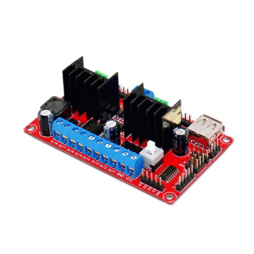
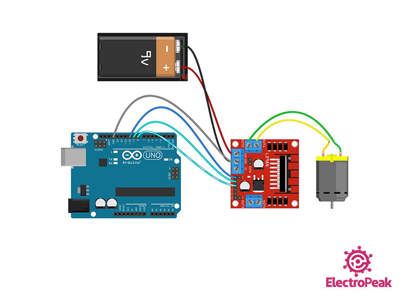
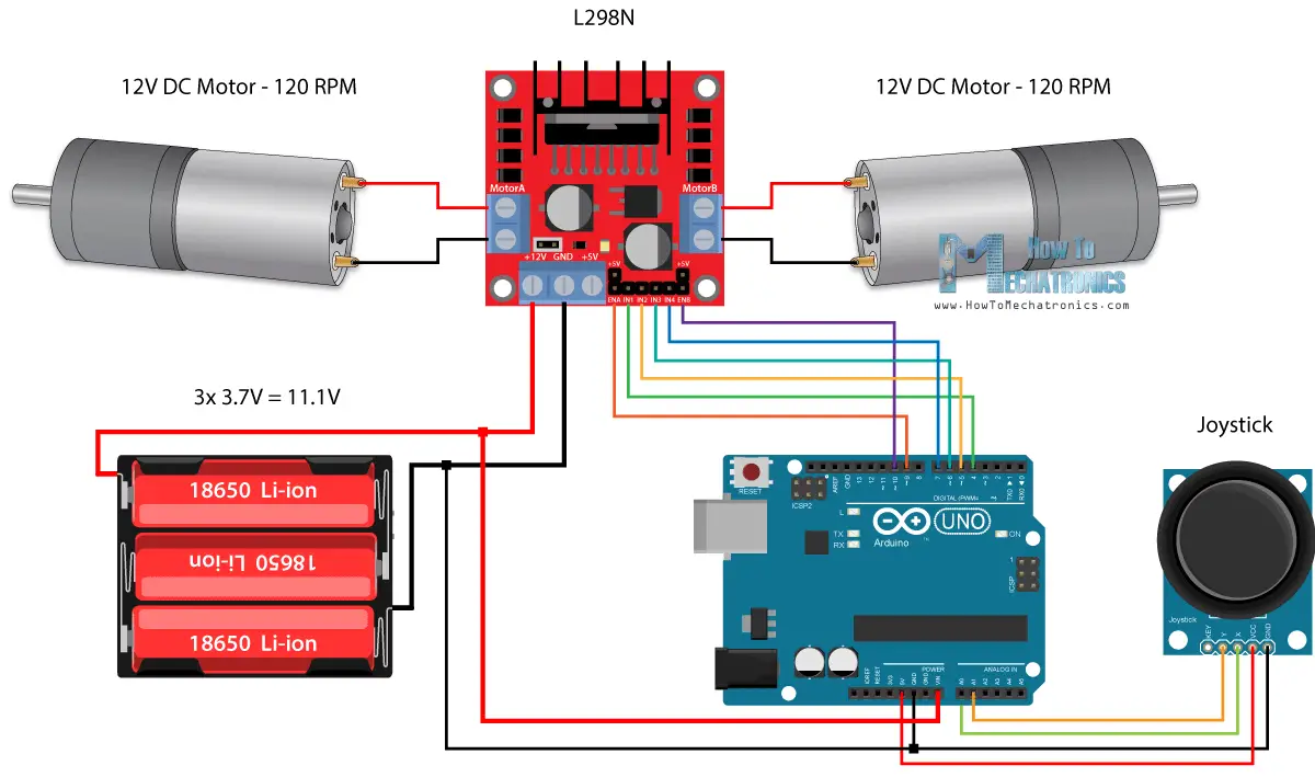
The module can drive DC motors that have voltages between 5 and 35V, with a peak current up to 2A.Motors Driver:It can drive one 2-phase stepper motor, one 4-phase stepper motor or two DC motors.Logic Input: EnableA/IN1/IN2/IN3/IN4/EnableB The L298N is a dual H-Bridge motor driver which allows speed and direction control of two DC motors at the same time. This module consists of an L298 motor driver IC and a 78M05 5V regulator. L298N Module can control up to 4 DC motors, or 2 DC motors with directional and speed control. This L298N Motor Driver Module is a high power motor driver module for driving DC and Stepper Motors. The motor speed is proportional to the duty cycle.
L298N MOTOR DRIVER WITH HOVERBOARD WHEELS DRIVER
Used with a dual bridge driver such as the L298N forms a complete microprocessor-to-bipolar stepper motor interface.ġ.If you send a HIGH signal to the enable 1 pin, motor A is ready to be controlled and at the maximum speed Ģ.If you send a LOW signal to the enable 1 pin, motor A turns off ģ.If you send a PWM signal, you can control the speed of the motor. The L297 integrates all the control circuitry required to control bipolar and unipolar stepper motors.

This module consists of an L298 motor driver IC and a 78M05 5V regulator. L298N Module can control up to 4 DC motors, or 2 DC motors with directional and speed control.

This L298N Motor Driver Module is a high power motor driver module for driving DC and Stepper Motors.
L298N MOTOR DRIVER WITH HOVERBOARD WHEELS SOFTWARE
The above hardware circuits and software programs have been tested and are completely practical.

Waveform diagram generated by L297Īccording to the waveform generated by L297, in fact, when the CPU port resources are not tight, the CPU can be used to simulate output. The speed of the motor speed can be controlled by the timer.įigure 3.
L298N MOTOR DRIVER WITH HOVERBOARD WHEELS DRIVERS
In this way, the two sets of drivers can be synchronized to achieve the effect of driving multiple motors at the same time. In addition, the terminal 1 of L297 is the synchronous terminal, which can be connected to the terminal 1 of another group of L297 and L298 drive circuits. Then, through the reasonable arrangement of the software, the purpose of controlling the motor to rotate in the expected direction is achieved. Ports P0~P4 are respectively connected to the corresponding control terminals of L297. The principle of L297+L298 drive wiring is shown in Figure 2. When two pieces of L297 are used to drive the two windings of a stepping motor through L298, and the Vref corresponding to each winding is changed through two D/A converters, a stepping motor subdivision driving circuit is formed. Due to the bipolar drive, the motor coil is fully utilized to enable into the motor can achieve the best drive.
L298N MOTOR DRIVER WITH HOVERBOARD WHEELS FULL
It is driven by a double full bridge mode. L298 is used to drive the power output of the stepper motor. Drive signal (A, B, C, D) and motor current settings. L297 is a stepper motor controller that is used to generate two-phase bipolar. It is driven by a constant current mode, and the peak current of each phase can reach 2A. L297 and L298 can be used to make a two-phase bipolar stepper motor drive circuit.

Standard stepper motor driver using L297 and L298 IC III L297 and L298 Hardware circuit 3.1 L297 Overview


 0 kommentar(er)
